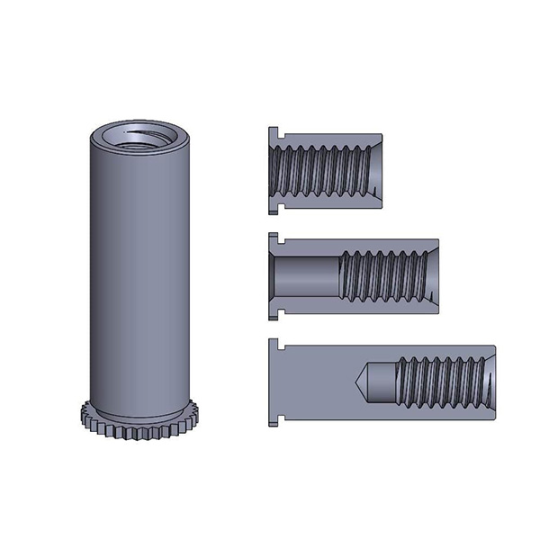
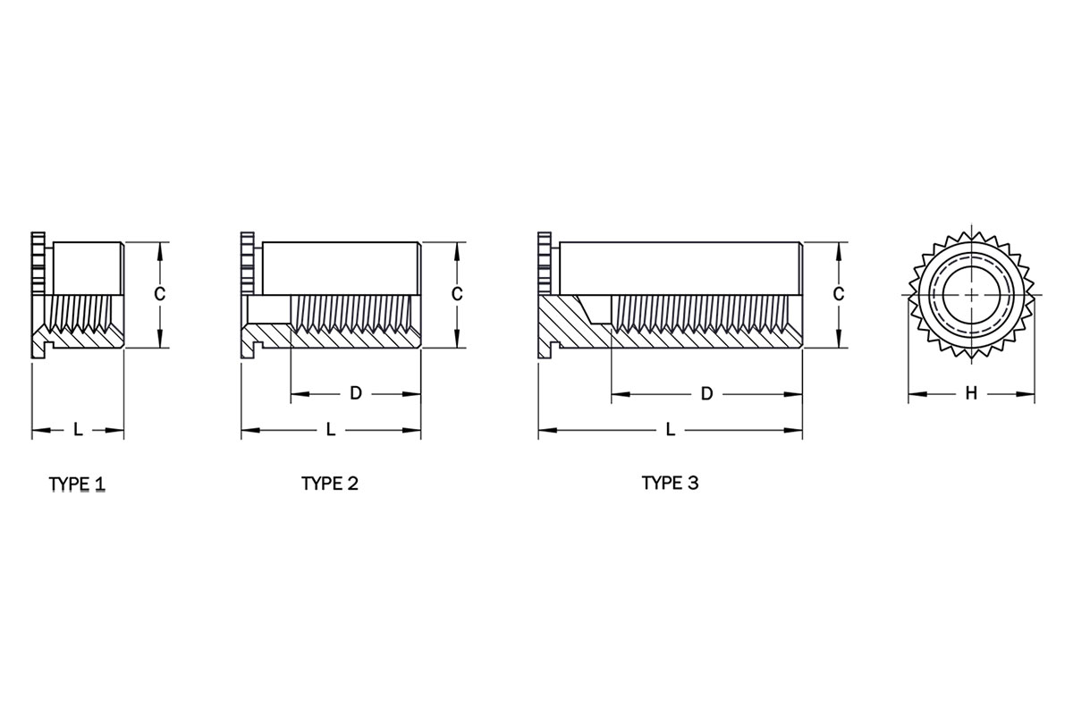
General
| Thread | Thread Code | Sheet | CMax. | DMin. | HNom. | ||
|---|---|---|---|---|---|---|---|
| Minimum Thickness | Hole Size | Minimum Distance Hole Center to Edge | |||||
| M1 x 0.25 (1) | M1 | 0.30 | 2.41 - 2.46 | 2.3 | 2.39 | 2.0 | 3.18 |
| M1.2 x 0.25 (1) | M1.2 | 0.30 | 2.41 - 2.46 | 2.3 | 2.39 | 2.4 | 3.18 |
| M1.4 x 0.3 (2) | M1.4 | 0.30 | 2.41 - 2.46 | 2.3 | 2.39 | 2.8 | 3.18 |
| M1.6 x 0.35 (3) | M1.6 | 0.30 | 2.41 - 2.46 | 2.3 | 2.39 | 3.5 | 3.18 |
| M2 x 0.4 (3) | M2 | 0.30 | 3.18 - 3.23 | 3.0 | 3.16 | 3.9 | 3.96 |
| M2.5 x 0.45 (3) | 3M2.5 | 0.94 | 4.22 - 4.30 | 3.2 | 4.20 | 5.2 | 4.92 |
| M3 x 0.5 (3) | M3 | 0.94 | 4.22 - 4.30 | 3.2 | 4.20 | 6.2 | 4.92 |
Length
| Thread Code | Length Code / Length | ||||||
|---|---|---|---|---|---|---|---|
| 2 | 3 | 4 | 5 | 6.35 | 7 | 8 | |
| M1 | 1.92-2.05 (1) | 2.92-3.05 (1) | 3.92-4.05 (2) | 4.92-5.05 (3) | 6.27- 6.40 (3) | 6.92- 7.05 (3) | 7.92- 8.05 (3) |
| M1.2 | 1.92-2.05 (1) | 2.92-3.05 (1) | 3.92-4.05 (2) | 4.92-5.05 (2) | 6.27- 6.40 (3) | 6.92- 7.05 (3) | 7.92- 8.05 (3) |
| M1.4 | 1.92-2.05 (1) | 2.92-3.05 (1) | 3.92-4.05 (1) | 4.92-5.05 (2) | 6.27- 6.40 (3) | 6.92- 7.05 (3) | 7.92- 8.05 (3) |
| M1.6 | 1.92-2.05 (1) | 2.92-3.05 (1) | 3.92-4.05 (1) | 4.92-5.05 (2) | 6.27- 6.40 (2) | 6.92- 7.05 (2) | 7.92- 8.05 (2) |
| M2 | 1.92-2.05 (1) | 2.92-3.05 (1) | 3.92-4.05 (1) | 4.92-5.05 (1) | 6.27- 6.40 (1) | 6.92- 7.05 (2) | 7.92- 8.05 (2) |
| 3M2.5 | 1.87-2.05 (1) | 2.87-3.05 (1) | 3.87-4.05 (1) | 4.87-5.05 (1) | 6.22- 6.40 (1) | 6.87- 7.05 (2) | 7.87- 8.05 (2) |
| M3 | 1.87-2.05 (1) | 2.87-3.05 (1) | 3.87-4.05 (1) | 4.87-5.05 (1) | 6.22- 6.40 (1) | 6.87- 7.05 (1) | 7.87- 8.05 (2) |
| Thread Code | Length Code / Length | |||||
|---|---|---|---|---|---|---|
| 10 | 12 | 14 | 16 | 18 | 19 | |
| M1 | 9.92-10.05 (3) | 11.92-12.05 (3) | – | – | – | – |
| M1.2 | 9.92-10.05 (3) | 11.92-12.05 (3) | – | – | – | – |
| M1.4 | 9.92-10.05 (3) | 11.92-12.05 (3) | – | – | – | – |
| M1.6 | 9.92-10.05 (3) | 11.92-12.05 (3) | – | – | – | – |
| M2 | 9.92-10.05 (3) | 11.92-12.05 (3) | 13.92-14.05 (3) | 15.92-16.05 (3) | ||
| 3M2.5 | 9.87-10.05 (3) | 11.87-12.05 (3) | 13.87-14.05 (3) | 15.87-16.05 (3) | 17.87-18.05 (3) | 18.87-19.05 (3) |
| M3 | 9.87-10.05 (2) | 11.87-12.05 (3) | 13.87-14.05 (3) | 15.87-16.05 (3) | 17.87-18.05 (3) | 18.87-19.05 (3) |
Material & Finish
| Material Code | Material Description | Finish Code | Finish Description | For Use in Sheet Hardness | ||
|---|---|---|---|---|---|---|
| HRB 70Max. | HRB 80Max. | HRB 88Max. | ||||
| ST (1) | Heat Treated1215 Carbon Steel | Z | Zinc (SC1) with Type III Clear Chromate per ASTM B633 | • | ||
| SS | 300-Series Stainless Steel | P | Passivated and/orTested per ASTM A967 | • | ||
| S4 (2) | Heat Treated 400-SeriesStainless Steel | P | Passivated and/orTested per ASTM A967 | • | ||
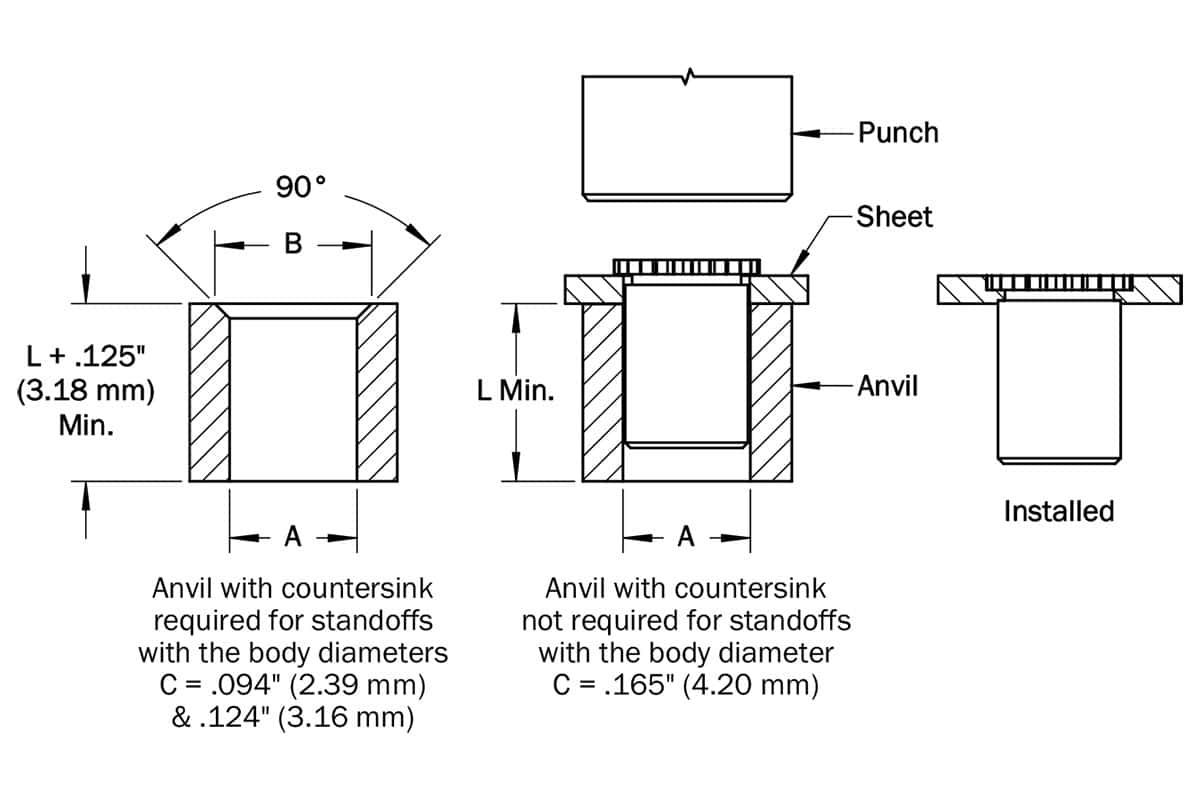
Installation
- Prepare correct sized mounting hole in sheet. Do not deburr edges.
- Insert standoff through hole in punch side of the sheet and into the anvil as shown.
- Squeeze the sheet and standoff head between parallel anvil and punch surfaces. Use only enough pressure to seat the standoff head flush with the sheet.
- Anvil with countersink is required for standoff with maximum body diameters.
- For installation in stainless steel, the sheet should be annealed and avoid standoff installation next to bends or other highly cold-worked areas. The hole punch diameter should be no greater than .001” (0.025mm) over the minimum recommend- ed mounting hole diameter and kept sharp to minimize work hardening around the hole.
Anvil and Punch Dimensions
| Standoff C Max.Dimension | A | B | Anvil Part Number | Punch Part Number |
|---|---|---|---|---|
| 2.39 | 2.84-2.89 | 2.46-2.51 | TL1268 | TL1287 |
| 3.16 | 3.60-3.65 | 3.22-3.27 | TL1269 | TL1287 |
| 4.20 | – | 4.30-4.38 | TL1087 | TL1287 |
Performance
| Thread Code | Stand. Matl. Code | Test Sheet Thickness | Test Sheet Material | |||||||||||
|---|---|---|---|---|---|---|---|---|---|---|---|---|---|---|
| 5052-H34 Aluminum | Cold-rolled Steel | 300-Series Stainless Steel | ||||||||||||
| Installation (kN) | Push-out (N) | Torque- out(N-m)(2) | Pull- thru(N)(2) | Installation (kN) | Push-out (N) | Torque- out(N-m)(2) | Pull- thru(N) (2) | Installation (kN) | Push-out (N) | Torque- out(N-m)(2) | Pull- thru(N) (2) | |||
| M1 M1.2 M1.4 M1.6 | SS | 0.30mm | – | – | – | – | 4.0 | 89 | 0.14 | 178 | (3) | (3) | (3) | (3) |
| 0.43mm | 2.7 | 89 | 0.14 | 178 | 4.5 | 156 | 0.18 | 330 | (3) | (3) | (3) | (3) | ||
| S4 | 0.30mm | – | – | – | – | – | – | – | – | 11.1 | 150 | 0.15 | 350 | |
| 0.43mm | – | – | – | – | – | – | – | – | 11.1 | 200 | 0.25 | 350 | ||
| M2 | SS | 0.30mm | – | – | – | – | 4.5 | 111 | 0.23 | 200 | (3) | (3) | (3) | (3) |
| 0.43mm | 3.1 | 111 | 0.23 | 200 | 4.9 | 178 | 0.28 | 378 | (3) | (3) | (3) | (3) | ||
| S4 | 0.30mm | – | – | – | – | – | – | – | – | 11.1 | 150 | 0.25 | 500 | |
| 0.43mm | – | – | – | – | – | – | – | – | 11.1 | 200 | 0.30 | 500 | ||
| 3M2.5 M3 | ST | 1.00mm | 3.1 | 223 | 1.1 | 1422 | 4.9 | 334 | 1.1 | 1587 | (3) | (3) | (3) | (3) |
| SS | 1.00mm | 3.1 | 223 | 1.1 | 1422 | 4.9 | 334 | 1.1 | 1587 | (3) | (3) | (3) | (3) | |
| Thread | ||||||||||
|---|---|---|---|---|---|---|---|---|---|---|
| 0-80 | 2-56 | 4-40 | M1 | M1.2 | M1.4 | M1.6 | M2 | M2.5 | M3 | |
| Max. Rec. Tightening Torque for Mating Screw | .65in-lbs | 1.3in-lbs | 3.8in-lbs | 0.019N-m | 0.036N-m | 0.057N-m | 0.084N-m | 0.175N-m | 0.28N-m | 0.44N-m |