TK, TM and TN self-clinching standoffs provide internal threads and spacing for thin metallic sheets. Pressing the standoffs into punched or drilled holes of ductile metal sheets displaces the host material into the engineered recesses of the standoffs and prevents the fasteners from rotating and removal. Following the instructions below results in a consistent and robust installation:
- Punch or drill hole in sheet. Do not deburr edges. See table below for sheet hardness recommendations.
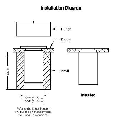
- Insert standoff through hole in sheet and into the anvil as shown in the diagram below.
- Squeeze the sheet and standoff head between parallel punch and anvil surfaces. Using the installation loads in the table on page 2 as a guide, use only enough pressure to seat the standoff head flush with the sheet. Punch and anvil should be made from hardened tool steel.
| Standoff Material Code | Material Description | For Use in Sheet Hardness | |||
|---|---|---|---|---|---|
| HRB 50 Max. | HRB 70 Max. | HRB 80 Max. | HRB 88 Max. | ||
| ST | Heat-treated Carbon Steel | • | |||
| SS | 300-Series Stainless Steel | • | |||
| AL | Aluminum | • | |||
| S4 | 400-Series Heat-treated Stainless Steel | • | |||
Inch
| Standoff “C” Nom. Dimension | Sheet Material | ||
|---|---|---|---|
| .060″ 5052-H34 Aluminum (lbs)1 | .060″ Cold-rolled Steel (lbs)2 | .050″ 300-Series Stainless Steel (lbs)3 | |
| .165 | 1100 | 2200 | 5500 |
| .212 | 1700 | 3300 | 9500 |
| .280 | 2400 | 4000 | 10500 |
Metric
| Standoff “C” Nom. Dimension | Sheet Material | ||
|---|---|---|---|
| 1.50mm 5052-H34 Aluminum (kN)1 | 1.50mm Cold-rolled Steel (kN)2 | 1.30mm 300-Series Stainless Steel (kN)3 | |
| 4.20 | 4.9 | 9.8 | 24.5 |
| 5.39 | 7.6 | 14.7 | 42.3 |
| 7.12 | 10.7 | 17.8 | 46.7 |
- Installation loads apply to ST, SS and AL stud material codes.
- Installation loads apply to ST and SS stud material codes. Studs with AL material code not recommended for installation in carbon steel sheets.
- Installation loads apply to S4 stud material code. Studs with ST, SS and AL material codes not recommended for installation in stainless steel sheets.
- Installation data represents average results for standoffs only when all installation specifications are strictly followed. Variations in panel hole size, thickness, material and installation methods will affect the loads. Pencom strongly encourages testing in the application.
- Refer to the latest Pencom TK, TM and TN standoff fliers for C dimensions.
