General
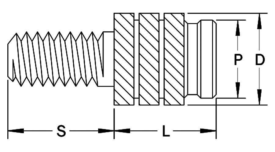
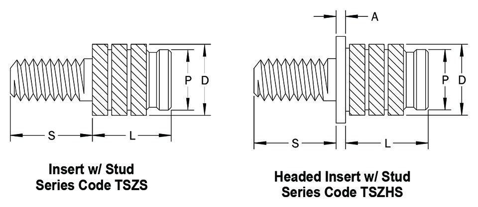
| Insert Thread | Insert Thread Code | L Insert Length | Insert Length Code | Boss | A Head Thickness | C Head Diameter | D Insert Diameter | P Pilot Diameter | |
| B Hole Dia. +.004 -.000 | W Wall Thickness Min. | ||||||||
| 2-56 | 256 | .162 | 162 | .122 | .063 | .020 | .187 | .131 | .117 |
| 4-40 | 440 | .208 | 208 | .150 | .079 | .023 | .217 | .165 | .146 |
| 6-32 | 632 | .247 | 247 | .181 | .098 | .029 | .250 | .196 | .178 |
| 8-32 | 832 | .292 | 292 | .213 | .098 | .035 | .281 | .228 | .209 |
| 10-24 | 1024 | .326 | 326 | .244 | .098 | .042 | .312 | .259 | .241 |
| 10-32 | 1032 | .326 | 326 | .244 | .098 | .042 | .312 | .259 | .241 |
| 1/4-20 | 2520 | .362 | 362 | .307 | .110 | .052 | .375 | .332 | .304 |
| 1/4-28 | 2528 | .362 | 362 | .307 | .110 | .052 | .375 | .332 | .304 |
| 5/16-18 | 3118 | .362 | 362 | .366 | .150 | .052 | .437 | .383 | .365 |
| 5/16-24 | 3124 | .362 | 362 | .366 | .150 | .052 | .437 | .383 | .365 |
| 3/8-16 | 3716 | .362 | 362 | .484 | .197 | .062 | .551 | .499 | .481 |
| 3/8-24 | 3724 | .362 | 362 | .484 | .197 | .062 | .551 | .499 | .481 |
Stud Length
| Stud Thread | Stud Thread Code | D Insert Diameter | S – Stud Length | |||||||||
| .187 | .250 | .312 | .375 | .437 | .500 | .625 | .750 | .875 | 1.000 | |||
| Stud Length Code | ||||||||||||
| 2-56 | 256 | .131 | 187 | 250 | 312 | — | — | — | — | — | — | — |
| 4-40 | 440 | .165 | 187 | 250 | 312 | 375 | 437 | — | — | — | — | — |
| 6-32 | 632 | .196 | 187 | 250 | 312 | 375 | 437 | 500 | — | — | — | — |
| 8-32 | 832 | .228 | 187 | 250 | 312 | 375 | 437 | 500 | 625 | — | — | — |
| 10-24 | 1024 | .259 | 187 | 250 | 312 | 375 | 437 | 500 | 625 | 750 | — | — |
| 10-32 | 1032 | .259 | 187 | 250 | 312 | 375 | 437 | 500 | 625 | 750 | — | — |
| 1/4-20 | 2520 | .332 | — | 250 | 312 | 375 | 437 | 500 | 625 | 750 | 875 | 1000 |
| 1/4-28 | 2528 | .332 | — | 250 | 312 | 375 | 437 | 500 | 625 | 750 | 875 | 1000 |
| 5/16-18 | 3118 | .383 | — | — | 312 | 375 | 437 | 500 | 625 | 750 | 875 | 1000 |
| 5/16-24 | 3124 | .383 | — | — | 312 | 375 | 437 | 500 | 625 | 750 | 875 | 1000 |
| 3/8-16 | 3716 | .499 | — | — | — | 375 | 437 | 500 | 625 | 750 | 875 | 1000 |
| 3/8-24 | 3724 | .499 | — | — | — | 375 | 437 | 500 | 625 | 750 | 875 | 1000 |