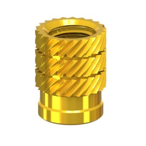
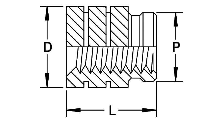
• 2D drawing of TSZ Thermoset Inserts designed for use in thermoset plastics.
  • TSZ dimension dwg
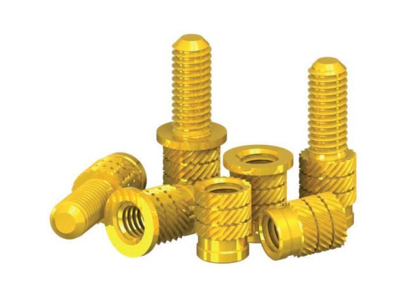
  • tsz featured 1
  • tsz thermoset zerts tech
  • 2D drawing of TSZ Thermoset Inserts designed for use in thermoset plastics.
  • TSZ dimension dwg
  • tsz featured 1
  • tsz thermoset zerts tech

TSZ Thermoset Inserts Inch


Features

  • Simple press–in installation.
  • Sharp helical knurls broach into thermoset materials to provide high torque–out resistance.
  • Self–aligning design.
  • Available in a wide variety of thread sizes, stud lengths and options.
Download PDF

Loading Parts

General
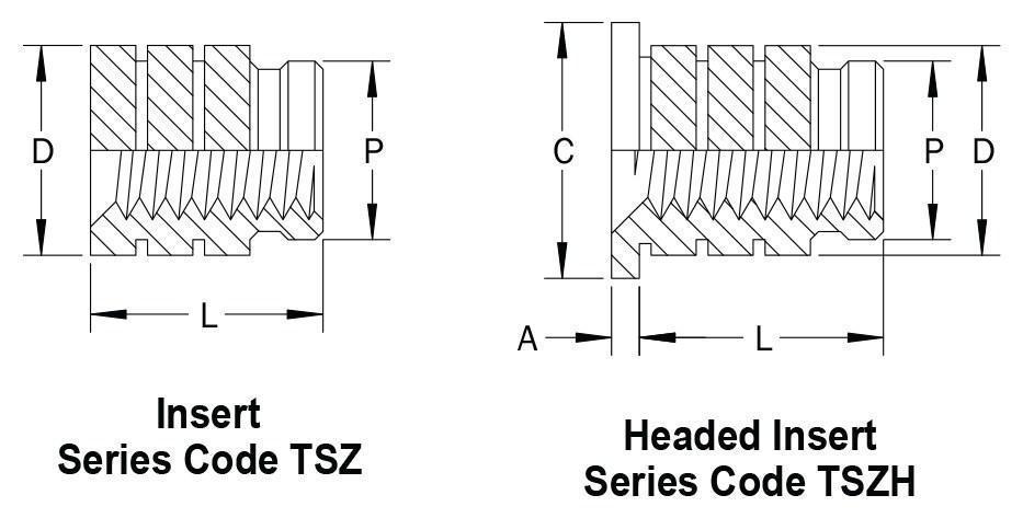
Insert Thread Insert Thread Code L Insert Length Insert Length Code Boss A Head Thickness C Head Diameter D Insert Diameter P Pilot Diameter
B Hole Dia. +0.10 -0.00 W Wall Thickness Min.
M2 x 0.4 M2 4.10 4.10 3.10 1.60 0.51 4.80 3.30 3.00
M2.5 x 0.45 M2.5 5.30 5.30 3.80 2.00 0.58 5.50 4.20 3.70
M3 x 0.5 M3 5.30 5.30 3.80 2.00 0.58 5.50 4.20 3.70
M3.5 x 0.6 M3.5 6.30 6.30 4.60 2.50 0.74 6.40 5.00 4.50
M4 x 0.7 M4 7.40 7.40 5.40 2.50 0.89 7.10 5.80 5.30
M5 x 0.8 M5 8.30 8.30 6.20 2.50 1.07 7.90 6.60 6.10
M6 x 1.0 M6 9.20 9.20 7.80 2.80 1.32 9.50 8.20 7.70
M8 x 1.25 M8 9.20 9.20 9.30 3.80 1.32 11.10 9.70 9.30
M10 x 1.5 M10 9.20 9.20 12.30 5.00 1.57 14.00 12.70 12.20

(1) all dimensions are in millimeters and reference unless toleranced

Boss Design Recommendation
The TSZ Thermoset Zert is designed to be installed into a straight hole with a 1° inclusive taper. The top of the hole should not be countersunk or counterbored as this will decrease the insert’s performance. The recommended hole size applies at the point reached by the bottom of the insert. Molded holes should be used wherever possible as drilled holes may result in diminished performance. Minimum boss wall thicknesses shown are for reference and may vary depending on the type of plastic.
Installation
Press the insert into the boss using a squeezing action– never a hammer blow. Allow the insert to rotate in the direction of the knurl during installation by using a punch with either a polished face or thrust bearing. Ensure that the insert maintains axial alignment during installation to prevent tilting which will induce side loads on the boss. Oversize boss holes weaken the insert’s self–aligning characteristics causing side loads which may lead to possible boss cracking.