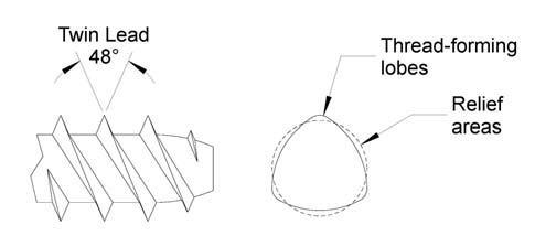
PENCOM’s PLAST48-2 screws incorporate a 48° flank twin lead thread with a trilobular body. The sharp coarsely-spaced threads provide a deep engagement in the plastic to reduce stress during thread forming; while the steep thread helix angle results in reduced assembly times and a higher stripping failure torque permitting easier tool adjustment between failure and thread forming torques. The three-lobed body design allows many plastics to cold-flow in between the lobes thus reducing hoop stress and resisting loosening due to vibration eliminating the need for costly inserts and lock washers.
Boss Design
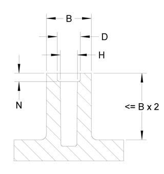
The boss design recommendations shown apply to the majority of applications. In some instances, excessive tangential stress encountered during assembly may require a reduction of the external boss diameter and/or increase of the boss hole diameter. In which case, the screw penetration depth should be increased to compensate for the reduced clamping performance.
PENCOM recommends performance validation testing in the application. For materials that are sensitive to environmental stress cracking, additional age testing should be conducted per the material manufacturer’s recommendations.
| Thread Size | Hole Diameter H | Boss Diameter B | Counterbore Diameter D | Counterbore Depth N | Screw Thread Engagement Length | |
|---|---|---|---|---|---|---|
| Soft Ductile Materials | Brittle Materials | |||||
| #2 | .076 | .080 | .223 – .267 | .097 | .009 – .018 | .178 – .267 |
| #4 | .100 | .106 | .310 – .372 | .132 | .013 – .025 | .248 – .372 |
| #6 | .122 | .128 | .360 – .432 | .152 | .013 – .026 | .288 – .432 |
| #8 | .149 | .158 | .455 – .546 | .190 | .016 – .031 | .364 – .546 |
| #10 | .175 | .185 | .523 – .627 | .217 | .018 – .036 | .418 – .627 |
| 1/4 | .224 | .240 | .683 – .819 | .281 | .025 – .050 | .546 – .819 |
| Thread Size | Hole Diameter H | Boss Diameter B | Counterbore Diameter D | Counterbore Depth N | Screw Thread Engagement Length | |
|---|---|---|---|---|---|---|
| Soft Ductile Materials | Brittle Materials | |||||
| M2.26 | 1.93 | 2.03 | 5.65 – 6.78 | 2.46 | 0.23 – 0.45 | 4.52 – 6.78 |
| M3.12 | 2.54 | 2.69 | 7.87 – 9.45 | 3.35 | 0.32 – 0.64 | 6.30 – 9.45 |
| M3.63 | 3.1 | 3.25 | 9.14 – 10.97 | 3.86 | 0.33 – 0.67 | 7.32 – 10.97 |
| M4.55 | 3.78 | 4.01 | 11.56 – 13.87 | 4.82 | 0.40 – 0.79 | 9.25 – 13.87 |
| M5.28 | 4.45 | 4.7 | 13.27 – 15.93 | 5.51 | 0.45 – 0.91 | 10.62 – 15.93 |
| M6.81 | 5.69 | 6.1 | 17.34 – 20.80 | 7.13 | 0.64 – 1.27 | 13.87 – 20.80 |
Assembly Torque
As clamping load increases, material relaxation and potential for stress cracking rise as well. Therefore, PENCOM strongly encourages using the minimum necessary tightening torque rather than the maximum that can be achieved.
Driver Speed
Friction between the screw threads and boss wall generates heat during installation. High driver rpm causes excessive heat that can melt the plastic and increase the likelihood of stripping failure during installation. As a guideline, 200-300 rpm generally results in a proper installation while maintaining high productivity. However, the driver rpm should be tested in the application and adjusted as necessary.

